This weekend I had reason to investigate the way the cables on a Roland electronic drum kit are wired to the connector block. If you’re unsure, I mean the wiring loom that comes with nearly all electronic kits and connects the various trigger pads to the digital ‘brain’. Only a few Roland kits don’t use this method of connection, relying instead on individual cables with 6mm jack plugs. The many kits that do have the loom (from TD-01DMK through to the mighty TD-27) usually have a variety of pads with either single triggers or dual triggers, hence the loom itself is made up of what appear to be a mixture of stereo and mono cables. If you’re not sure, a stereo cable appears to have two black rings around the jack, and a mono only has one, as you’ll see in the picture.
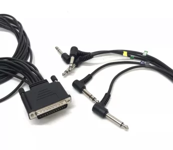
In fact, the stereo cable has three connectors on it, separated by the black insulating rings, and the mono cable has two – meaning inside a stereo cable are three smaller wires and inside a mono cable are two. The ‘anatomy’ of a jack plug is either ‘TRS’ or just ‘TS’. That’s ‘Tip’, ‘Ring’ and ‘Sleeve’ for Stereo or just ‘Tip’ and ‘Sleeve’ for mono. You can easily pull these apart and see the soldered wires connecting to each part of the jack itself. The ‘tip’ and ‘ring’ connectors are generally the ones that signals go along, whilst the ‘sleeve’ is normally a ‘ground’ wire that does not carry a signal to the ‘brain’. Thus a stereo jack can carry two signals, a mono cable carries one, but both types of jack need to be ‘grounded’.
On the other end of the cable is a 25 pin D-type connector, similar to the ones we used to see on computer printers before USB became the standard connection type.
An electronic drum kit has ‘sensors’ or ‘triggers’ – basically, combinations of piezoelectric transducers and switches. A ‘piezo’ is simply a small electronic device that converts pressure (such as from a drum stick striking the drum surface) into electrical signals. Using combinations of piezos and switches, it’s possible to assign individual sounds to each, and a combination sound if they are activated simultaneously. The Roland wiring loom only uses stereo and mono cables, so each pad can have a maximum of two triggers, or only one. It won’t surprise you to learn that the wiring loom has five of each jack type, because simple mathematics tells us that this equates to 25 individual wires connecting to the 25 pins in the other end (3×5 = 15, and 2×5= 10, making 25 in total). This allows pads like a snare drum to use a stereo cable and get three different sounds, whilst a kick drum only needs a mono cable because it’ll only make one sound. The strength with which the pad is struck is also able to be detected, and this ‘velocity’ factor can help adjust the sound accordingly. A gentle tap on the snare top produces a ‘ghost’ note, whilst an almighty great thwack can produce a much more snappy snare drum sound. Both hits are activating the same trigger, but at different levels.
So it was, with all this in mind, that I reached for my trusty multimeter to find out where each cable went to in the D-Type connector block, because that will affect how the digital ‘brain’ receives the signal, and therefore what default sounds it will assign to the pads themselves. If you want to make your own custom 25-pin connector, it’s as well to know which pins go where. There are videos on the internet where people customise the wiring loom by cutting each cable and adding a jack socket to make it easier to manage routing all the wires around the drum set ‘frame’. Here’s one:
This makes it much easier to handle the wiring on the kit itself, but takes a bit of bravery, given that a new wiring loom would set you back about £70, depending on where you shop if you make a mess of it. You also need to be able to solder, or know someone who can.
I guess I was just plain curious about all this and want to know where things went. It turns out, it’s not what you might think! Looking at a 25 pin D-type connector there are two rows of pins, with 13 along the top row, and 12 along the bottom. Starting at pin 1 and simply going along each pin, allocating a pad and a connection would be logical (Kick drum, T, then R, then S, for example), but it turns out that it’s not quite that simple. 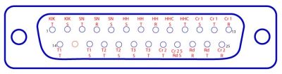
It all starts off like that – Kick drum, then snare, then Hi-Hat and controller, but check out the T, R and S… not exactly a simple sequence, almost as if someone was not paying too much attention when putting the very first one together. And what happened to ‘Crash 2’? Very odd layout, in my opinion.
Also, check out pin 15. It doesn’t appear to be used at all, whilst pin 22 has a double connection – and there could be two possible explanations for this. One might be as simple as allowing for expansion later, although these looms have been around for a fair while now, and in the same configuration for all kits, regardless of pads and numbers of triggers. The other explanation could be that ‘back in the day’ printer cables used pin 15 for error reporting, and this legacy is why pin 15 on the Roland loom doesn’t get used for a pad signal.
You’ll also wonder why it is possible to double the connection on pin 22, but not on other pins. The doubling up is for the sleeve on both pads, and as we know that is a ‘ground’ connection which does not carry a signal for a sound to be assigned. But what if we doubled up ALL of the ground connections, how many more pads could we put on a kit? Well, apart from the one already coupled, there are 8 more ‘sleeve’ connections which would release 4 more pins, and if one of those had to be a doubled up ground connection, three could be used for audio signals – meaning there is at least one more dual zone pad, and one more single zone pad possible. So why didn’t Roland do this? I am speculating that at the time the wiring loom was designed, the format of electronic drums was fairly well set, and ever since then Roland has kept all pads they make to be compatible with all of the different ‘brains’ or modules. In an attempt to maintain this compatibility, the very first cable looms are now the pattern, even for the quite different modules and possibilities that we have today. It would be possible for ALL of the ground wires to be combined into far fewer pins, and connect those ground pins to a common ‘rail’ inside the module itself, thereby enabling a far bigger drum kit to be created, and fewer restrictions on the drummers who want to expand their setups. Of course, nothing is that simple, and whilst I don’t actually know the real reason behind this curious pin arrangement, I am sure the good folks at Roland will have an explanation!